EZ-Wired Connection Concept
Introduction
Traditional wiring within a fixture has been done using ‘wire wrap’, or similar direct connection technologies (like soldering), from the pogo pin receptacle to a pylon connector receptacle, to connect to external equipment, using individual wires. Such connection technologies have been around since the start of fixtures and have many disadvantages as highlighted below:
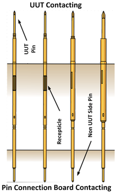
The introduction of ‘wireless’ / ‘double ended’ pogo pins provides a much more effective connection method that is particularly suited for use with a J-Testr which is directly mounted inside a fixture. We called this the “EZ-Wired” connection method, and it consists of the below 3 elements:
|
Other elements such as the “Pin alignment support” and the “Pogo board spacers” are standard parts that are provided with customised fixtures when specifying 'wireless' receptacles. It is always important that the fixture vendor provides sufficient ‘Pin connection board’ mounting points such that adequate support is given to the PCB to avoid flexing and stress. Always be sure to discuss this with the fixture vendor and be sure that they understand the connection method you are seeking to implement.
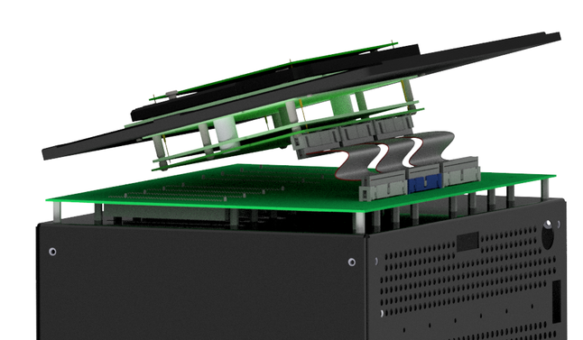
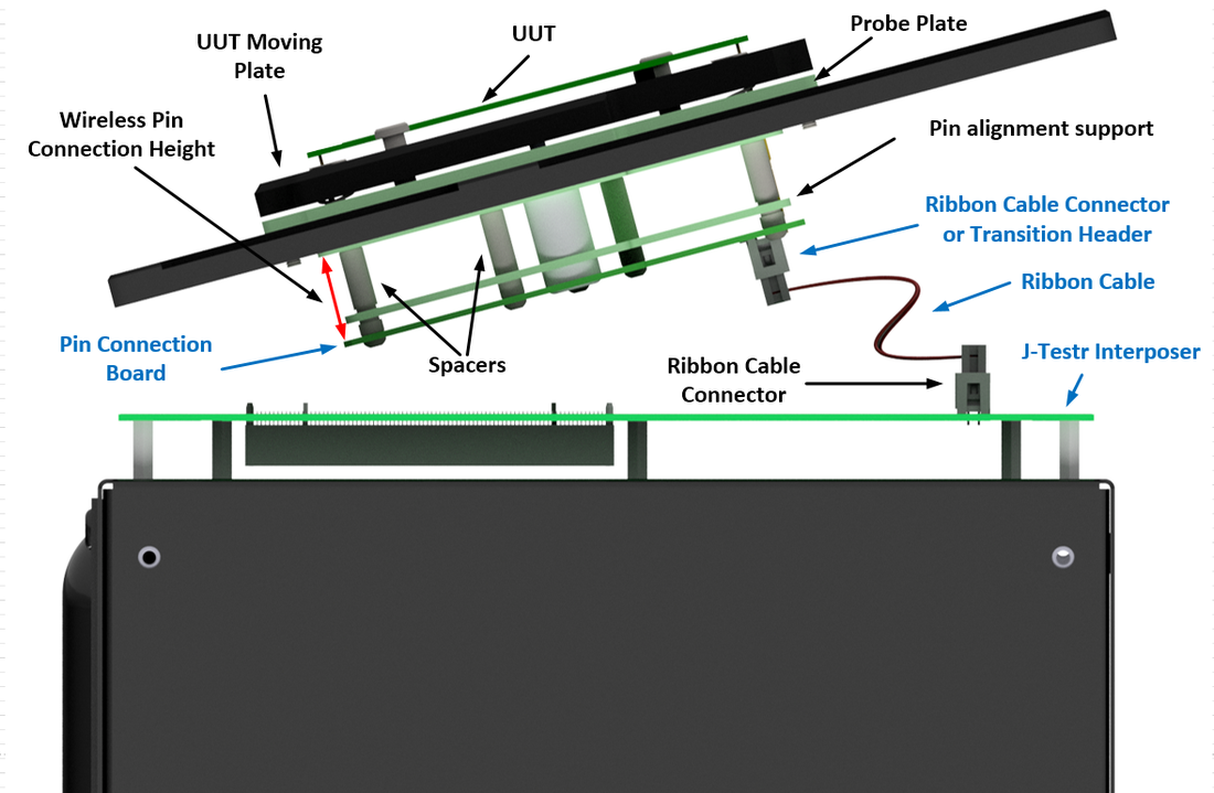
The below picture show the “EZ-Wired” connection concept and all the main elements:
The below picture show the “EZ-Wired” connection concept and all the main elements:
Pin Connection Board
The pin connection board is used to take the connection from the non UUT end of the ‘wireless' receptacle to a standard low-cost ribbon cable connector, or even a ribbon cable transition header.
The pin connection board is mounted, using standard PCB standoff pillars, underneath the fixture probe plate and at a defined distance depending on the fixture type. This defined distance allows connection by compression of the sprung pin at the end of the 'wireless' receptacles.
The size of the pin connection board and its location depends on the application. Eiger Design can provide example DXF files and/or 3D STEP files for reference. If required Eiger Design can provide a full turnkey connection solution or just a connection board or the customer can easily design all items for themselves.
J-Testr Standard Interposer
As the name suggests this is the standard interposer that is required for all J-Testr systems and is mounted, in the normal way, on top of the J-Testr system.
On the J-Testr interposer all connections that are required to be routed to the UUT are taken to standard ribbon cable headers corresponding directly to those that are on the pin connection board.
On the J-Testr interposer all connections that are required to be routed to the UUT are taken to standard ribbon cable headers corresponding directly to those that are on the pin connection board.
Standard Ribbon Cable
|
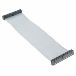
With the “EZ-Wired” connection concept, ribbon cables are used as the cabling between the J-Testr interposer and the pin connection board.
Ribbon cables are widely available, easy to use, low-cost, have good signal integrity characteristics and are extremely reliable. They are available in multiple pitches with the most common being 1.27mm, but are also available in pitches as low as 0.5mm if space is an issue. Even though ribbon cables are not designed specifically for power, multiple connections can be used to route power connections. It is recommended that at least 3 connections are used per 1A of current to reduce voltage drops and increase fault tolerance. As both the J-Testr interposer and the pin connection board are horizontal, the physical routing of the ribbon cable is extremely neat and the length can be kept to a minimum to maximise signal integrity and reduce voltage drops. |


