J-Safe Electronic protection features
- Comprehensive safety/protection circuitry
- 100% system wide 'Fail safe' protection scheme
- Ultra-fast re-action time
- No user software intervention required
- Can eliminate the requirement of ICT prior to Functional Test
- Simple to set-up and use
- External ‘User’ safety circuitry easily added with ’Go-Safe’ Signal
Technical Overview
When powering up or testing a new UUT for the first time, or when testing a reworked or repaired UUT, there is always a risk that an unknown fault may damage the UUT, possibly irreparably. Damage to a UUT at first power up can be very costly because a lot of time and expense has already been incurred to build the product to this level. Simple process faults can cause such errors (e.g. missing/wrong component value or solder-balls or shorts). For this reason, high speed protection circuits are extremely important to protect the UUT from damage, particularly during the first ever power up and test.
When powering up or testing a new UUT for the first time, or when testing a reworked or repaired UUT, there is always a risk that an unknown fault may damage the UUT, possibly irreparably. Damage to a UUT at first power up can be very costly because a lot of time and expense has already been incurred to build the product to this level. Simple process faults can cause such errors (e.g. missing/wrong component value or solder-balls or shorts). For this reason, high speed protection circuits are extremely important to protect the UUT from damage, particularly during the first ever power up and test.
|
Protection circuitry, such as Over-Voltage Protection (OVP) and Over-Current Protection (OCP), can help avoid such issues, but careful consideration to the design of such circuits is required to provide a solution that is both fast and effective. For example, in an over-voltage (OV) condition, which can cause damage in a matter of micro-seconds (us)*, what is the best cause of action? Traditional techniques, such as a 'crowbar' seen in many bench top supplies, could allow excessive currents to flow through the UUT circuitry from the offending OV source, thus causing further damage. At Eiger Design, we believe the only truly effective solution is to shut-down all sources of energy into the UUT as quickly as possible.
|
In a test system with multiple power supplies, all supplies should be shut-down, not just the 'offending' supply, because the other supply/supplies may still be generating the un-wanted conditions. For example a 12V supply rail shorted to a 5V supply rail by the UUT would most likely cause an overvoltage on the 5V, but may not cause an over-current on the 12V supply. Shutting down just the 'offending' 5V supply (and not the 12V one also) would maintain an overvoltage on the UUT 5V rail. To provide the best safety, from all fault conditions, the test system must shutdown ALL supplies as rapidly as possible.
|
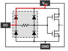
Unfortunately the safety story does not end with just shutting down the UUT power supplies as quickly as possible, because other stimulation sources (IO, DAC, communications, etc) can also force current to flow into the UUT. This is especially the case because ESD protection diodes are extremely common on most device IOs. When the UUT supplies are turned ‘off’, current can flow through these diodes, potentially even burning out the diode, and can cause different or latent faults that are often extremely hard to detect, or that may not appear until the UUT is in service.
|
Within the J-Testr Core, the J-Safe mechanism provides a fast-reacting hardware signal to the whole J-Testr Core to place it into a ‘safe' state. In this state, all potential energy sources connected to the UUT are turned off. The J-Safe process occurs at hardware speeds, and without any user intervention, avoiding the normal software and communication protocol delays that could allow higher energy transfer and thus further damage to the UUT
|
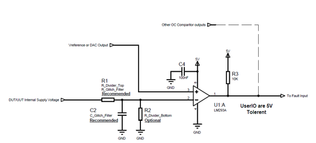
The J-Safe mechanism also provides the option for user-driven external hardware ‘GoJSafe’ signals per peripheral card**. This allows for user-specific and customised external protection circuitry on the J-Testr Core interposer. An example would be to monitor local point of load (POL) regulators that power FPGA or processor core voltages. These normally ‘low voltage’ supplies can cause damage if they become over-voltage due to incorrect components being fitted, or because of short circuits to high voltage supplies (e.g. 3.3V VCCIO shorted to 1.2V VINT). One or more simple comparator circuits can be used to monitor as many parameters as required.
|
The J-Safe mechanism has also been designed to enable simple tracking of the cause of the condition. A dedicated ‘JSafe’ register, per peripheral card**, tells the user if the peripheral card:
a) Is responding to a J-Safe condition (either detected by itself, or from elsewhere in the system).
b) Has detected the J-Safe condition itself. (e.g. overvoltage detected on a PSU feeding a UUT)
c) Has been triggered by an external user-supplied ‘GoJSafe’ signal.
If a peripheral card is found to have detected the J-Safe condition, the user can simply look at the other fault registers for the specific Peripheral Card type, and/or the user supplied ‘GoJSafe’ signal, and print/report the errors as required.
* Due to the ‘punch through’ effect damaging the oxide layer within a semiconductor
** Does not include JTAG only Cards, however JTAG only cards do react to the internal J-Safe signal.
** Does not include JTAG only Cards, however JTAG only cards do react to the internal J-Safe signal.


