ADC / DAC Peripheral Card
Features• +/- 10V input/output range
• Separate 0.1% ADC and DAC references • 16 bit DAC system • 8 DAC channels in 2 banks of 4 • Selectable internal or external DAC reference • DAC calibration possible for higher accuracies • 16 bit Ultra low-noise ADC system • 8 differential or 16 single ended channels (or mixed) • Up to 256 differential or 256 single-ended channels (with Muxing) • Programmable PGA and digital filter • Programmable scans with MIN/MAX/Average/RMS Results • Multiple trigger sources (inc. external) and delays • High impedance over-voltage protected inputs • +/-12V supplies & controls for external buffers/muxes • 8 User I/Os with UART, SPI, I2C, PWM, GoJ-Safe & GPSM features |
| ||
About
The ADC/DAC peripheral card incorporates both a precision ADC system and a precision DAC system.
ADC System
The ADC system uses a very low-noise 16bit ADC with a matching 0.1% tolerance reference to achieve high measurement accuracy and noise levels below +/-0.5 LSB. A very large dynamic range is achieved using a Programmable Gain Amplifier (PGA) which allows the user to set signal gains between x0.125 and x128. This not only allows very small signals to be measured using the full 16 conversion bits, but also allows signals as large as +/-10V to be measured, thus giving maximum measurement flexibility.
The ADC system is capable of automatically scanning between 1 and 256 analogue channels. For each ‘scan’ channel the PGA gain and multiplexing setup can be individually configured. For single-ended measurements, one end of the signal can be simply programmed to connect to the analogue ground. This enables the ADC system to measure all different types of signal during its scan cycles.
The hardware on-board the ADC/DAC peripheral card supports up to 8 differential channels, for precision measurements, or up to 16 single-ended channels, for less critical measurement or a combination of both. If more ADC channels are required, then any of the GPIO signals can be configured as extra multiplexer control lines to enable additional multiplexers to be added to the interposer or connection card. Adding extra multiplexers allows the ADC system to measure up to 256 differential or single-ended signals.
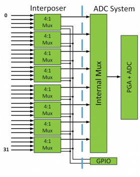
Increasing ADC to 32 Differential or 64 Single ended measurement
Results from the 256 ADC channels are buffered so the user only has to read a single register to get the measurement required. Scanning can software controlled, triggered, or continuous depending on the user’s needs.
Programmable scans (1 to 65535), for each channel, and advanced measurement features (Min/Max/Average/RMS) round off the sophisticated yet simple to use features provided by the ADC/DAC Peripheral Card
Programmable scans (1 to 65535), for each channel, and advanced measurement features (Min/Max/Average/RMS) round off the sophisticated yet simple to use features provided by the ADC/DAC Peripheral Card
DAC System
The DAC function allows for testing of UUT ADC systems, comparator circuitry, or any other circuitry that requires a fine resolution, high stability, programmable voltage level. The DAC system has two bank of four 16-bit high-resolution protected outputs. The system uses an industry-standard highly integrated DAC IC designed specifically for electronic test systems. The ADC/DAC Peripheral card allows the user access to the powerful test features this IC offers by allowing easy/quick access to the IC internal registers.
The ADC/DAC Peripheral card enables the user to select the reference for each of the two DAC banks. The reference can be either the on-board low-noise high accuracy 0.1% reference, or be connected to an external reference provided by the user on the interposer.
The ability to select different references gives the user maximum flexibly to tune the output voltage range to the needs of the UUT. This is especially true as the DAC IC allows the output to be either x4 or x6 of the selected reference input.
If extremely high accuracy is required for the testing of high accuracy ADC systems, the DAC IC provides powerful calibration features to tune the output accuracy to very low tolerances.
User IO Features
Finally, as with all bus connected peripherals, the ADC/DAC peripheral provides 8 general purpose User IOs which can be used to control and/or read custom circuitry on the interposer. The IOs can provide special hardware functions such as 16-bit PWM, UART, SPI, I2C and GPSM (General Purpose Signal Monitor for measuring freq/duty/pulse-width etc.) that can be multiplexed to any of the IO pins.