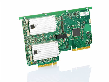
Dual Load Peripheral Card
Features• Dual 8A 40W loads or single 16A 80W
• 1V to 60V working input range • Programmable current set value with 1mA resolution • Transient mode (Load stepping) • Floating architecture allows negative supplies • Independent hardware over-temperature interlocks • Programmable threshold supply voltage sensing • Programmable rapid over-power shutdown • Accurate voltage and current monitoring • Remote voltage sensing (HV and LV ranges) • 8 User I/Os with UART, SPI, I2C, PWM, GoJ-Safe & GPSM features |
| ||
About
The high efficiency cooling system inside the J-Testr mechanics enabled the design of this 80W capable dual load card that truly sets the J-Testr apart from the competition. This function brings new levels of UUT testing allowing users to fully test their on-board power supplies, or even to test dedicated power supply designs. Combined with the supply peripheral card, the load peripheral card allows the following power supply testing to be achieved without any bulky external equipment:
> Full current and over-current
> Load regulation
> Line regulation
> Efficiency
> Transient response
Two independently controllable 40W loads gives the user the ability to test two lower power supplies (e.g. 12V at 3.3A // 5V at 8A) or a single higher power supply (e.g. 5V at 16A). In fact up to 2 load cards can be fitted to a J-Testr system allowing a maximum of 160W of power loading per J-Testr system. If more loads are required, and concurrent test is not required, then the GPIO lines can be used to control relays on the interposer to multiplex multiple power supplies.
A true floating architecture allows the load card to be used for negative power supplies hence not restricting its use to positive only supplies like some systems.
A transient mode steps the load between 100% and 33% of the set current at a very high rate of change enabling the testing of transient response. The 100% to 33% stepping is chosen to allow the easy testing of a typical 25% to 75% load step. i.e. for an 8A supply, set the load to 6A and step between 6A and 2A which equates to 75% and 25% of the 8A supply under test.
As you would expect for a J-Testr peripheral card, the loads have been designed with both test and safety in mind, hence protection features such as independent rapid Over-Power (OP) and Over-Temperature (OT) have been implemented to avoid damage occurring to the internal power MOSFETs. All fault signals are latched and can be read from registers so the user can easily track down the cause and report it to the operator.
Fully integrated precision current and voltage monitoring, with remote sense, allows the output power of the supply under test to be measured as close to the UUT as possible. The remote sense helps the user to eliminate measurement errors due to voltage drops in high current paths, making power measurement significantly more accurate.
Other features like programmable external supply voltage sensing, that will automatically turn the load on/off depending on the supply voltage level, give the load card a refined set of functions not even available on bulky bench-top models.
Finally, as with all bus connected peripherals, the ADC/DAC peripheral provides 8 general purpose User IOs which can be used to control and/or read custom circuitry on the interposer. The IOs can provide special hardware functions such as 16-bit PWM, UART, SPI, I2C and GPSM (General Purpose Signal Monitor for measuring freq/duty/pulse-width etc.) that can be multiplexed to any of the IO pins.