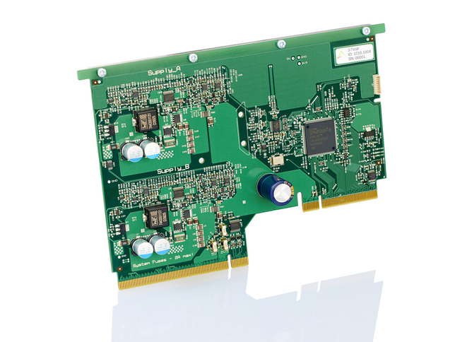
LV / HV Supply Peripheral Card
Features• LV Dual 2.5V to 15V 5A supplies (24V Input)
• HV Dual 2.5V to 30V 3A supplies (48V Input)* • Programmable output with 1mV setting resolution • Low ripple and noise • Digitally programmable ramp up/down control • Remote sense • On/Off control with programmable sequencing • Programmable independent OVP and OCP • Latched fault reporting • Rapid turn-off of all supplies on fault event (J-Safe) • Programmable Power-Good indication • Accurate/stable voltage and current monitoring • Current Measurement Monitor (‘IMM’ - Monitor inrush/glitches)** • 8 User I/Os with UART, SPI, I2C, PWM, GoJ-Safe & GPSM features *V2 only, 5V to 30V 3A supplies (48V Input) on V1 Cards **New generation V2 Cards only |
| ||
About
The supply peripheral card gives customers all the power supply features they would expect from a modern bench supply, all contained within the small footprint of a J-Testr peripheral card. In fact, with advanced features such as digitally programmable ramp rates, sequencing, and generic IO lines, these supplies offer capabilities only seen on more advanced expensive bench top supplies.
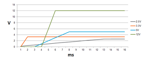
These advanced control features allow the customer to simulate complex external supply profiles, enabling testing of internal voltage monitoring chips, to prove that the UUT will function as expected under the most extreme power-up cases. The diagram, below, shows an example of a complex power-up profile. This is easily achieved using two J-Testr supply peripheral cards, by adjusting the ramp rate of each individual supply, and the time sequence between each supply turning on.
These advanced control features allow the customer to simulate complex external supply profiles, enabling testing of internal voltage monitoring chips, to prove that the UUT will function as expected under the most extreme power-up cases. The diagram, below, shows an example of a complex power-up profile. This is easily achieved using two J-Testr supply peripheral cards, by adjusting the ramp rate of each individual supply, and the time sequence between each supply turning on.
Accurate current and voltage monitoring/measurement is achieved using a 16 bit (noise free) ADC system. This provides the user with a measurement resolution of 1mV/1mA across the whole measurement range and high nominal accuracies of 0.125% (Voltage) and 0.25% (Current). These accurate measurements enable the user to determine if the UUT is consuming the expected current/power under different test conditions. The voltages are differentially measured at the remote sense points, hence eliminating load related voltage drops that can introduce significant power measurement errors.
The supply cards have been designed with test in mind, and ‘J-Safe’ protection features such as independent over-voltage and over-current are included. However, what is very important when functionally testing a UUT is how the power supply/supplies behave when a fault condition occurs. With the J-Testr, ALL supplies will turn off extremely rapidly during a J-Safe event, greatly reducing the risk of damage to the UUT. This is especially important if a high voltage rail is shorted to a low voltage rail, because catastrophic damage can typically occur when one supply is not present but the others remain.
Many UUTs include local ‘Point of Load’ regulators that can fail, producing damaging over-voltage conditions to expensive microprocessor and/or FPGAs. To help protect against these conditions, peripheral card GPIOs can be configured to provide the user a trigger input to the J-Safe mechanism. Custom user fault protection can then be easily added to the interposer using a very simple comparator circuit to trigger the same system-wide J-Safe mechanism.
All fault events are latched and can be read from registers so the user can easily track down the cause and report it to the operator.
A new current measurement monitor (IMM), on V2 hardware, gives the user the ability to sample the current at a much-improved rate to determine minimum, maximum and average currents over a monitoring period. The current measurement monitor can be configured for continuous operation, whilst the supply is in the steady ‘on’ state, or just for monitoring during the time when the supply is ramping its voltage
Finally, as with all bus connected peripherals, the ADC/DAC peripheral provides 8 general purpose User IOs which can be used to control and/or read custom circuitry on the interposer. The IOs can provide special hardware functions such as 16-bit PWM, UART, SPI, I2C and GPSM (General Purpose Signal Monitor for measuring freq/duty/pulse-width etc.) that can be multiplexed to any of the IO pins.


